


How should I verify if the efficiency of the cooling system in the all-electric extrusion blow molding machine meets the standards?
At our factory, we frequently see clients struggle with inconsistent cycle times caused by hidden cooling inefficiencies 1. Poor heat removal often destroys profitability, turning a high-speed machine into a bottleneck regardless of its motor speed.
To verify cooling system efficiency, calculate the Reynolds number to ensure turbulent flow (>4,000) and measure the water temperature differential between supply and return lines. Ideally, this difference should stay between 3–5°F (1.5–3°C) to confirm adequate heat removal capacity without flow restriction.
Here is how we validate these specific metrics on our production floor to ensure machine performance 2.
How do I measure the actual flow rate and temperature drop across the mold cooling channels?
When we commission machines for clients, we never rely on guesswork for water settings 3. Incorrect flow rates often cause invisible cycle delays that significantly eat into daily production targets and profit margins.
You must verify that the cooling channel flow achieves a Reynolds number above 4,000 to prevent laminar flow insulation. Additionally, measure the pressure drop specifically across the machine’s integrated manifold versus the mold itself to rule out parasitic pressure losses in the plumbing.

To truly understand what is happening inside your mold, you must look beyond simple volume metrics (Gallons Per Minute) and focus on flow dynamics. In our engineering tests, we prioritize achieving Turbulent Flow. If the water flows too smoothly (Laminar Flow), a boundary layer of warm water clings to the mold channels, acting as an insulator. By ensuring a Reynolds number greater than 4,000, we break this boundary layer, maximizing heat transfer.
The Temperature Differential Rule
A practical way to check this on the shop floor is by measuring the temperature differential ($\Delta T$) between the supply and return water lines.
- Ideal Range (3–5°F / 1.5–3°C): This indicates the flow rate is balanced with the heat load. The water is moving fast enough to carry heat away efficiently.
- High Differential (>5°F / 3°C): The water is spending too much time in the mold. The volumetric flow rate is too low, or the channels are undersized.
- Low Differential (<2°F / 1°C): The flow is too high (wasting pump energy) or, worse, scale buildup is preventing the water from absorbing heat at all.
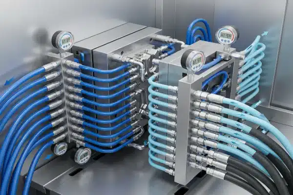
Pressure Drop in All-Electric Designs
In compact all-electric machines, internal plumbing is often routed tightly to accommodate servo motors. We advise measuring the pressure drop ($\Delta P$) specifically across the machine’s integrated water manifold versus the mold itself. We have seen instances where undersized internal plumbing creates high "parasitic pressure loss." This falsely limits flow to the mold, meaning your pump might be powerful, but the pressure is lost before it ever reaches the cooling channels.
Flow Regime Comparison
| Flow Type | Reynolds Number | Characteristics | Heat Transfer Efficiency |
|---|---|---|---|
| Laminar Flow | < 2,300 | Smooth, layered movement. Warm water sticks to walls. | Düşük (Insulates mold) |
| Transient Flow | 2,300 – 4,000 | Unstable mixture of smooth and chaotic flow. | Orta (Unpredictable) |
| Turbulent Flow | > 4,000 | Chaotic mixing. Breaks thermal boundary layer. | Yüksek (Optimal cooling) |
Does the machine design prevent heat transfer from the electric motors to the mold area?
We often notice that high-torque servo motors 4 generate significant heat during continuous operation. If uncontrolled, this heat migrates directly into the machine structure, fighting against your cooling system and destabilizing the process.
Verify the presence of thermal isolation plates or air gaps between the clamping servo motors and the machine platens. Conduct an energy balance audit by comparing electrical input against water heat removal to identify any unaccounted thermal bleed affecting the mold base.

İçinde hydraulic machines 5, the oil circulates and carries a significant portion of the machine’s generated heat away to a heat exchanger. However, in all-electric extrusion blow molding machines, that heat mechanism does not exist. The large servo motors responsible for clamping tonnage are often bolted directly to the platens.
The Conductive Heat Problem
If we do not isolate these components, the heat from the motors conducts through the metal directly into the mold base. This is disastrous for cooling efficiency. You might be pumping chilled water into the mold, but the machine itself is heating the mold from the outside.
- Visual Inspection: Look for distinct thermal isolation plates (usually a composite material) or engineered air gaps between the motor housing and the machine casting.
- Temperature Checks: Use a surface thermometer on the platen near the motor mount. It should not be significantly hotter than the rest of the frame.
The Energy Balance Audit
To deeply verify efficiency, we perform an "Energy Balance" audit.
- Calculate the total electrical energy input (Extruder shear heat + Heater bands + Motor load).
- Calculate the heat removed by the cooling water (Flow rate $\times$ $\Delta T$).
- Compare the two.
In a well-designed all-electric machine, the heat removed by the water should closely match the heat introduced by the polymer (shear + heaters). If there is a massive discrepancy, it often points to "thermal bleed"—meaning heat is soaking into the machine frame or motors are running inefficiently hot, adding load that the chiller shouldn’t have to handle.
Heat Source Management
| Heat Source | Hydraulic Machine Path | All-Electric Machine Risk | Mitigation Strategy |
|---|---|---|---|
| Extrusion Heat | Removed by Mold Cooling | Removed by Mold Cooling | Standard Chiller Sizing |
| Clamping Friction | Removed by Hydraulic Oil | Trapped in Motor/Platen | Thermal Isolation Plates |
| Motor Heat | Removed by Hydraulic Oil | Conducts to Frame | Active Air Cooling / Fans |
What specific cooling capacity is required to maintain the shortest possible cycle time?
Our engineers always calculate cooling time 6 against the polymer’s physical limits rather than arbitrary machine settings. A machine running slower than the material allows is wasting money every second it operates.
Calculate the required cooling time against the polymer’s theoretical thermal diffusivity limit. If the machine requires significantly longer than the material’s solidification time to prevent warpage, the cooling system is substandard. Also, check for Euromap 82.2 integration to modulate pump speed dynamically.

The ultimate test of a cooling system is whether it can keep up with the material science. Every polymer, such as HDPE or PP, has a specific "thermal diffusivity"—the rate at which heat can travel through it. There is a theoretical minimum time required to cool a bottle of a specific thickness.
Benchmarking Against Theory
If your calculation shows that an HDPE bottle with a 1mm wall thickness should cool in 8 seconds, but your machine requires 12 seconds to eject a stable part, the cooling system is the bottleneck.
- Mold Material: Confirm that high-conductivity alloys, such as Beryllium Copper (BeCu), are inserted in critical areas like the neck and bottom pinch-offs. These areas hold the most heat. Steel cuts costs but slows down heat transfer significantly.
- Cycle Time Reality: If you have to extend the cycle just to prevent the bottles from warping after ejection, the heat extraction rate is insufficient.
Smart Cooling Integration
Modern verification involves checking the machine’s "brain." We look for Euromap 82.2 veya OPC UA integration capabilities. In advanced all-electric machines, the controller should talk to the external pump.
Instead of running the pump at 100% all day (wasteful), the machine modulates the pump speed based on the real-time cycle status. It ramps up flow during the cooling phase and ramps down during mold open/close. This dynamic cooling ensures the flow matches the heat load, maintaining the shortest possible cycle time without overworking the chiller.
Material Conductivity vs. Cooling Speed
| Mold Insert Material | Thermal Conductivity (W/m·K) | Relative Cooling Speed | Uygulama Alanı |
|---|---|---|---|
| P20 Steel | ~30 | Baseline (Slow) | General Cavity Body |
| Aluminum (7075) | ~130 | 4x Faster than Steel | Prototype / Low Volume |
| Beryllium Copper | ~105 – 130 | 3.5x Faster than Steel | Neck & Bottom Pinch-offs |
| Ampcoloy 940 | ~208 | 7x Faster than Steel | Critical Hot Spots |
How can I verify that the cooling manifold design ensures uniform temperature distribution?
We use thermal cameras 7 during factory acceptance tests to catch invisible problems that gauges miss. A blocked channel or poor design creates specific hot spots that ruin bottle quality and consistency.
Utilize thermal imaging cameras on ejected bottles immediately after demolding to identify specific hot spots. These indicate blocked channels, scale buildup, or poor circuit design. Even a 0.3mm mineral deposit layer can decrease heat transfer efficiency by up to 40%.

Uniformity is just as important as capacity. You can have a massive chiller, but if one side of the mold is 10 degrees hotter than the other, your bottles will warp, causing leaks and rejects.
HDPE bottle 9
The Thermal Camera Test
The most effective verification method we use is capturing a thermal image of the bottle immediately after it falls from the mold.
- What to look for: The temperature gradient should be relatively smooth.
- Red Flags: If you see a distinct bright "hot spot" on the side or bottom of the bottle, it acts as a proxy for the mold condition. It tells you exactly which cooling channel is blocked, bubbled (air lock), or scaled up.
- Interpretation: If the bottle neck is hot but the body is cold, check the flow to the neck inserts. If one cavity is hotter than the other in a multi-cavity setup, your manifold is unbalanced.
The "Fouling Factor" Audit
We cannot overstate the impact of water quality. We verify the "fouling factor" by inspecting the channels for rust or mineral scale.
- The 0.3mm Rule: A mineral deposit layer of just 0.3mm acts like an insulator, decreasing heat transfer efficiency by up to 40%.
- This creates a vicious cycle: The operator lowers the chiller temperature to compensate, wasting energy, but the heat still cannot cross the scale barrier.
- Doğrulama: Inspect the internal manifold and hoses. If you see rust or white calcium deposits, the machine’s cooling efficiency specifications are theoretically invalid until cleaned.
Sonuç
Verifying cooling efficiency requires looking beyond the chiller rating. By measuring Reynolds numbers, isolating motor heat, and using thermal imaging, we ensure the machine delivers maximum output and profitability.
heat removal 10
Dipnotlar
- Official guidance on identifying and mitigating inefficiencies in industrial cooling systems. ↩︎
- Scientific overview of factors affecting machine performance and efficiency in engineering. ↩︎
- Technical solutions for managing water flow and pressure in industrial manufacturing environments. ↩︎
- Product documentation for high-performance servo motors used in precision industrial machinery. ↩︎
- International standards for the design and safety of hydraulic fluid power systems. ↩︎
- Academic resources on calculating cooling rates and thermal processes in product engineering. ↩︎
- Official NIST resources on the application of thermal imaging for industrial measurement. ↩︎
- Industry standards for water testing and quality control in commercial and industrial applications. ↩︎
- Technical specifications for high-density polyethylene resins used in industrial blow molding. ↩︎
- General background on the principles of heat removal in thermodynamic and industrial processes. ↩︎


0 Yorum