


How can I ensure perfect compatibility between the mold and the machine when purchasing an all-electric extrusion blow molding machine?
At our facility, we often see customers struggle because they purchased a mold and a machine separately without checking how they interact. You invest heavily in high-efficiency all-electric equipment, but if the mold interface doesn’t align physically or functionally, you face costly downtime. Ensuring these two assets work together requires looking beyond basic dimensions.
To ensure compatibility, you must verify the platen mounting pattern (SPI vs. EUROMAP), confirm the minimum shut height matches your mold thickness, and validate that the die head center distance accounts for thermal expansion. Additionally, ensure the machine’s ejection and core pull capabilities align with your mold’s mechanical design.
Let’s examine the specific technical checkpoints you need to verify before finalizing your equipment order.
Does the physical mounting interface match your mold’s specifications?
When we prepare a machine for shipment, the most common delay we encounter involves the platen interface. If we build a machine for European standards and the customer tries to mount a US-standard mold, production cannot start. You need to verify these physical connections early in the procurement process.
You must confirm whether the machine follows SPI or EUROMAP hole patterns to avoid needing expensive adapter plates. Furthermore, for electric toggle systems, verify your mold thickness exceeds the machine’s minimum shut height limit. If the mold is too thin, the toggle mechanism cannot physically lock.

Understanding Platen Standards
The global plastics industry generally follows two main standards for mounting holes: SPI (Society of the Plastics Industry), common in North America, and EUROMAP, common in Europe and parts of Asia.
These standards dictate the size and spacing of the threaded holes on the platens. If your mold backplates are drilled for SPI (inches) but the machine platen is drilled for EUROMAP (metric), the bolts will not line up. While we can manufacture adapter plates, they reduce your available daylight (opening stroke) and add unnecessary cost.
The Rigid Limit of Electric Toggles
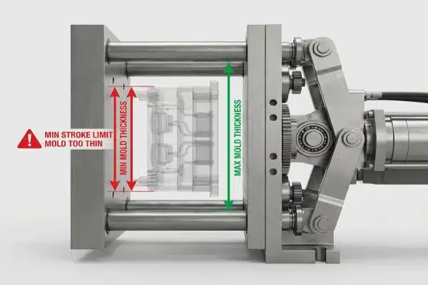
Unlike hydraulic clamping systems, which can often be forgiving regarding mold thickness, all-electric toggle systems have a hard mechanical limit known as the Minimum Shut Height.
If your mold is thinner than this specification, the toggle arms cannot extend fully to lock the mold. The machine simply won’t close. You must calculate the stack height of your mold carefully. If it is too thin, you will need to install permanent spacer plates on the mold back to bridge the gap.
Overhead Clearance Risks
Another physical constraint involves the vertical clearance. In shuttle machines, the mold moves back and forth under the die head. We advise checking the distance between the highest point of your mold (including lift rings and water fittings) and the parison cutter. If this clearance is too tight, you risk a collision during the shuttle movement.
Table: Physical Interface Checklist
| Характеристика | What to Check | Potential Consequence of Mismatch |
|---|---|---|
| Mounting Pattern | SPI vs. EUROMAP vs. JIS | Requires expensive, heavy adapter plates. |
| Shut Height | Machine Min. vs. Mold Thickness | Machine cannot clamp; requires spacer plates. |
| Vertical Clearance | Top of mold vs. Parison Knife | catastrophic collision during shuttle movement. |
Will the parison and blow pin alignment remain precise during operation?
We pride ourselves on the precision of our servo-driven movements, but the machine can only be as accurate as the setup allows. A common issue we troubleshoot involves misalignment that only appears after the machine heats up. You must account for physics, not just blueprints.
Parison alignment depends on matching the die head center distance to your mold cavities, specifically accounting for thermal expansion at operating temperatures. You must also ensure the blow pin station has a vertical calibration window that matches your mold’s shear steel height for consistent neck finishes.

The Thermal Expansion Factor
One of the most overlooked aspects of multi-cavity compatibility is Center Distance (CD). This is the distance between the nozzles on the die head and the distance between the cavities in your mold.
On paper, these might look identical. However, your mold is chilled (10°C – 15°C), while the die head runs hot (180°C – 200°C). Steel expands approximately 1mm per meter at these temperatures. If you have a wide die head, the nozzle centers will physically move outward as the machine heats up.
When we configure a machine, we need to know if your mold drawing specifies the Center Distance at "cold state" or "operating temperature." If this isn’t calculated correctly, the parison will not fall into the center of the cavity, leading to uneven wall thickness.
Blow Pin Calibration Windows
All-electric machines use servo motors for the blow pin carriage. This offers great precision but requires the mold to fall within a specific "calibration window."
You must check the height of the shear steel (striker plate) on your mold.
- Too Low: The blow pins may reach their maximum servo stroke before compressing the neck flash, resulting in poor cutting.
- Too High: The blow pins might crash into the mold before the servo drive completes its motion, causing a torque alarm or damaging the pins.
Table: Thermal Expansion Impact
| Die Head Width | Temperature Delta | Approx. Expansion | Result if Ignored |
|---|---|---|---|
| 200 mm | 180°C | ~0.25 mm | Minor wall variation. |
| 500 mm | 180°C | ~0.60 mm | Noticeable parison shift. |
| 1000 mm | 180°C | ~1.20 mm | Parison hits mold edge; impossible to run. |
Can the all-electric system handle your mold’s auxiliary requirements?
In our experience exporting to the US and Europe, we find that customers often assume an all-electric machine works exactly like their old hydraulic ones. This assumption leads to problems when the mold requires auxiliary functions that simply aren’t there. You need to map out your utility connections carefully.
All-electric machines generally lack hydraulic power units, so molds requiring hydraulic core pulls need auxiliary servo motors or portable pumps. Additionally, verify that water manifold thread types match your fittings and that the electric ejection stroke length is sufficient to fully clear parts from the mold.

The "No-Hydraulic" Trap
This is the most critical compatibility check for complex molds. If your mold uses hydraulic core pulls (cylinders used to unscrew caps or move side inserts), you cannot run it on a standard all-electric machine. The machine has no oil and no pump.
To fix this, you have two options:
- Retrofit the mold: Replace hydraulic cylinders with electric motors (expensive).
- Add a portable HPU: Purchase a standalone Hydraulic Power Unit to actuate the cores, integrated into the machine’s control signals.
Water and Air Connections
Don’t ignore the plumbing. We have seen installs halted because the machine came with Метрика water manifolds, but the customer’s mold hoses had NPT (American) fittings. You also need to check the location of these manifolds. If the machine’s water supply is on the operator side, but your mold’s inputs are on the rear, you will need to fabricate long extension hoses, which can kink and restrict flow.
Ejection Synchronization
On hydraulic machines, ejection is often just a "bang-bang" motion. on all-electric machines, it is a precise servo movement. You must ensure:
- Pattern Alignment: The machine’s ejection bars must line up with the knockout holes on your mold.
- Stroke Length: Electric ejectors often have a fixed maximum stroke. If you are making a deep bucket that requires a long ejection push to clear the core, verify the servo arm has enough travel.
Are the machine dynamics capable of handling your specific mold weight and pressure?
We design our machines to be robust, but physics ultimately dictates performance. An all-electric machine relies on kinetic energy and braking resistors. If you overload the carriage or under-spec the clamping force, the machine will alarm out or produce bad parts.
You must verify that the servo shuttle motor can brake effectively with your specific mold weight to avoid voltage alarms. Simultaneously, calculate the total projected area including flash to ensure the machine’s clamping force is strong enough to prevent the mold from breathing under pressure.
Shuttle Inertia and Motor Braking
In electric shuttle machines, the carriage moves the mold back and forth very quickly. This requires the motor to accelerate and then brake aggressively.
If your mold is significantly heavier than the machine’s "Standard Mold Weight" rating, the regenerative energy created during braking may be too much for the drive system. This usually triggers a "DC Bus Overvoltage" alarm. To run a heavy mold, you might have to slow the cycle time down drastically, defeating the purpose of buying a high-speed electric machine.
Calculating True Projected Area
Many buyers make the mistake of calculating clamping force based only on the bottle’s dimensions. You must calculate the Projected Area of the bottle plus the flash (pinch-off areas).
When the air is blown in, pressure applies to the flash just as much as the bottle.
- Formula: (Bottle Area + Flash Area) × Shrinkage Force (300-500 psi).
- If the result exceeds the machine’s tonnage, the mold will "breathe" (open slightly). This causes thick parting lines, inconsistent bottle weights, and wasted material.
Table: Dynamic Load Analysis
| Параметр | Calculation Basis | Risk if Incorrect |
|---|---|---|
| Сила зажима | Total Area (Part + Flash) | Mold breathing; heavy flash lines. |
| Shuttle Weight | Mold Mass + Cooling Water | DC Bus Overvoltage; forced slow cycles. |
| Platen Deflection | Mold Size vs Platen Size | Uneven pinch-off; premature mold wear. |
Заключение
Ensuring compatibility between your mold and an all-electric machine is about more than just checking dimensions. You must account for thermal expansion, verify auxiliary connections like core pulls, and ensure the machine’s dynamics can handle the mold’s weight and pressure. Taking time to audit these factors now will save you from expensive modifications later.


0 Комментариев