


In our assembly hall, we frequently see clients struggle with inconsistent wall thickness despite investing in premium electric servomotor elétrico 1 sopro Computational Fluid Dynamics (CFD) 2. The culprit is often a generic die head design that ignores specific specific resin's viscosity curve 3 resin properties. We know that a machine is only as good as the parison Parison Control (MOOG) 4 it extrudes, so precise specification is vital.
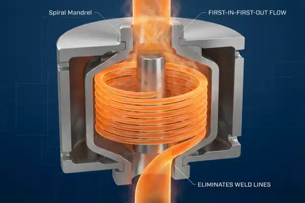
To optimize die head flow channels, demand Rheological CFD reports using your specific resin's viscosity curve to verify shear rates. Explicitly request Spiral Mandrel geometry to eliminate weld lines and specify a "First-In-First-Out" flow path to minimize residence time and prevent material degradation in electric extrusion processes.
Let’s break down the technical questions and specifications you must discuss with your supplier to ensure your tooling matches the precision of your new electric machine Chrome Plating 5.
How do I verify the flow channel efficiency before manufacturing?
When we engineer solutions for LEKA clients, we insist on seeing simulation data because trial-and-error is simply too costly for high-speed electric production lines Thermal Expansion 6. Relying on "standard" designs often leads to performance bottlenecks that servos cannot correct.
You must require a Computational Fluid Dynamics (CFD) analysis that proves uniform shear rates below 100 1/s. Furthermore, ask for Pressure Drop (ΔP) calculations at maximum output to ensure the head’s restriction doesn’t force the electric servo motor to operate near its torque limit, causing overheating.

A necessidade da simulação reológica
Never accept a supplier's claim that a design is "tested" without seeing the data. In the era of all-electric machines, where precision is paramount, the die head must be mathematically verified before a single piece of steel is cut. You should mandate a Rheological Simulation Report.
This report must be run using the viscosity curve of your specific resin (e.g., HMW-HDPE vs. PP). HMW-HDPE vs. PP 7 A generic simulation is useless because different plastics flow differently under pressure. You are looking for proof that "dead spots"—areas where plastic stops moving—do not exist. In our testing, dead spots are the primary cause of degradation and long color changeover times.
Pressure Drop and Servo Torque
One critical aspect often overlooked by buyers is the relationship between the die head's Pressure Drop (ΔP) and the electric machine's servo motor.
- Hydraulic machines typically have brute force to push through restrictive heads.
- Electric machines rely on servo motors that have specific torque curves.
If the flow channels are too restrictive (high pressure drop), your electric extruder has to work harder. This forces the servo motor to operate near its peak torque limit continuously. This leads to overheating, "torque limit" alarms, and reduced energy efficiency. By requesting the calculated ΔP at maximum output, you ensure the head is "energy-matched" to the machine's drive system.
Geometry: Spider vs. Spiral Mandrel or Cardioid
The geometry of the channel dictates the strength of the bottle. We strongly advise against older "Spider" designs for high-quality applications.
Table 1: Comparison of Die Head Geometries
| Recurso | Spider Die Head (Traditional) | Spiral Mandrel / Cardioid (Recommended) |
|---|---|---|
| Flow Path | Melt is split by metal legs ("spiders") supporting the core. | Melt flows through spiraling channels that overlap layers. |
| Bottle Strength | Creates vertical "weld lines" (weak points) where melt rejoins. | No weld lines; creates a homogenous, strong parison. |
| Visual Quality | Visible lines on the bottle surface. | Smooth surface, ideal for gloss finishes. |
| Back Pressure | Generally lower, but flow is less uniform. | Higher, requiring efficient design to match electric servos. |
What design features prevent material degradation and surface defects?
We often troubleshoot "black specks" for customers using other brands, and this issue almost always stems from poor residence time management within the head. Even the most expensive electric machine cannot fix degraded plastic caused by a poorly designed flow path.
Specify a flow path designed for "First-In-First-Out" (FIFO) movement to eliminate dead spots where carbon builds up. Additionally, define internal surface roughness metrics, such as Ra < 0.02 µm with Chrome or Titanium Nitride coatings, to minimize friction and prevent sharkskin defects at high extrusion speeds.

Managing Residence Time
For heat-sensitive materials like PVC, PC, or even standard HDPE running at high temperatures, the time the plastic spends inside the hot die head is critical. This is known as Tempo de Residência.
You need to ask for the calculated residence time distribution graph. The goal is a strict "First-In-First-Out" (FIFO) flow path. If plastic lingers in the head (a "Last-In-First-Out" scenario), it burns and turns into carbon. These carbon deposits eventually break loose, appearing as black specks in your bottles. In steady-state operations, a FIFO design ensures that the material entering the head now is the material leaving the head moments later, keeping the melt fresh.
Surface Finish and Coatings
In electric extrusion, we often run at higher speeds to maximize output. However, high speeds create high friction between the plastic and the metal wall. If the friction is too high, the plastic "stutters" as it exits, causing a rough surface texture known as "melt fracture" or sharkskin.
To prevent this, you must be specific in your contract regarding the internal surface finish.
- Standard Polish: Ra 0.04–0.08 µm (Acceptable for industrial jerry cans).
- Optical Polish: Ra < 0.02–0.04 µm (Required for cosmetic bottles).
Furthermore, requesting specific coatings can drastically improve flow. Chrome Plating is the industry standard, but for abrasive materials or high-speed electric lines, Titanium Nitride (TiN) coatings offer superior hardness and lower friction coefficients.
Erasing "Melt Memory"
Plastic has "elastic memory." If it is squeezed through a complex channel, it wants to snap back to its original shape after leaving the die. This causes the parison to swell unpredictably, fighting against your electric servo's attempt to control the parison length.
To fix this, the die head must have a Relaxation Chamber or sufficient "Land Length." This is a straight section at the very end of the nozzle. It allows the plastic to "relax" and forget the stress of the flow channels before it exits. If this section is too short (low L/D ratio), you will struggle with unstable parison swinging and inconsistent weights.
Table 2: Defect Troubleshooting via Die Head Design
| Defect Symptoms | Root Cause in Design | Required Specification |
|---|---|---|
| Black Specks | Dead spots causing material burn. | FIFO Flow Path & Streamlined Hangers. |
| Sharkskin | High wall friction at exit. | Ra < 0.02 µm Polish + Chrome/TiN Coating. |
| Die Swell | Plastic memory not erased. | Extended Land Length (Relaxation Chamber). |
| Parison Curving | Unbalanced flow velocity. | CFD-verified Flow Balance Simulation. |
How does the mechanical design impact maintenance and machine precision?
Our service team knows that a die head taking four hours to disassemble kills profitability, so we prioritize modular stack designs that allow for easier cleaning. Maintenance downtime is a hidden cost that you must address during the design phase.
Confirm the die head uses a modular stack design allowing individual plate disassembly for rapid cleaning without removing the entire assembly. Also, verify the inclusion of ceramic thermal insulators at the mounting interface to prevent heat transfer from distorting the precision alignment of the electric machine’s clamping platen.

Modular "Stack" Design for Cleaning
Traditional die heads are often solid blocks that require you to unbolt the entire heavy assembly from the extruder just to clean the internal channels. This is dangerous and time-consuming.
When negotiating, ask to see the "Exploded View" drawing. You are looking for a Modular Stack design. This means the distribution plates and mandrel are stacked like pancakes. You should be able to remove the bottom die ring and pull out the internal flow plates individually while the main body remains bolted to the machine.
- Benefit: Drastically reduces color change time (from hours to minutes).
- Benefit: Easier to polish scratches or inspect for damage.
Thermal Isolation is Critical
This is a specific issue for high-precision all-electric machines. The die head operates at 200°C+ (400°F+), while the machine's clamping platen and frame must remain cool to maintain geometric precision.
If the hot die head is bolted directly to the machine frame without protection, heat transfers into the metal casting. This causes Thermal Expansion.
- The mounting plate expands, shifting the die head center.
- The mold alignment shifts relative to the parison.
- You get bottles with uneven necks or handle flash.
You must verify that the design includes Ceramic or Composite Thermal Insulators at the mounting interface. This acts as a heat break, keeping the heat in the plastic and away from your precision machine mechanics.
Table 3: Maintenance & Mechanical Checklist
| Recurso de design | Função | Why it Matters |
|---|---|---|
| Modular Stack | Allows disassembly by layer. | Saves 2-3 hours during deep cleaning. |
| Thermal Insulator | Blocks heat transfer to frame. | Maintains 0.01mm alignment accuracy. |
| Hinged Heater Bands | Easy access to wiring. | Faster heater replacement if one fails. |
| Hardened Tip | Replaceable tip/bushing. | Prevents replacing the whole mandrel due to wear. |
What specific tooling solutions handle complex bottle shapes and layers?
In our experience exporting to Europe, standard round tooling often fails on rectangular bottles, requiring excessive servo programming that slows down the cycle. The right tooling strategy can mechanically solve problems that electronics struggle to fix.
For non-round containers, inquire about "Ovalized" or Profiled Tooling to mechanically shape the parison thickness at the corners before extrusion. For multi-layer applications, request Interfacial Instability data to ensure layer ratios remain uniform during the rapid speed ramping characteristic of electric servo extruders.

Profiled (Ovalized) Tooling
If you are producing a rectangular jerry can or an oval cosmetic bottle using a perfectly round die setup, you will encounter a problem: the corners of the bottle will be thin, and the flat panels will be thick.
Operators usually try to fix this with Parison Control (MOOG) programming. However, excessive programming causes the parison to "pulse" violently, limiting your cycle speed.
A better approach is Profiled Tooling.
- The die bushing is shaped (ovalized) to place more plastic in the areas that will become the bottle corners.
- This is a mechanical solution that happens before the plastic leaves the head.
- It reduces the reliance on extreme servo programming, allowing your electric machine to run faster and smoother.
Multi-Layer Stability (Co-Ex)
If you are buying a machine for Co-Extrusion (e.g., placing recycled material in the middle layer), the flow channel design is even more complex.
Electric machines are dynamic; they speed up and slow down rapidly. You need data on Interfacial Instability. This ensures that the layers stick together and maintain their ratio (e.g., 10% Outer / 80% PCR / 10% Inner) even when the extruder ramps speed. If the channel design is poor, the layers will break up or create "wave" patterns inside the bottle wall, ruining the aesthetics and structural integrity.
Conclusão
A precision electric machine requires a precision die head to function correctly. By prioritizing CFD verification, FIFO flow pathse maintenance-friendly modular designs, you ensure your investment delivers consistent quality rather than constant troubleshooting.
Notas de rodapé
1. Provides comprehensive information on servomotors. ↩︎
2. Provides an overview of CFD analysis. ↩︎
3. Explains the importance of viscosity in understanding a resin’s flow behavior. ↩︎
4. Moog is a supplier of parison control systems. ↩︎
5. Provides a general overview of the chrome plating process. ↩︎
6. Explains the concept and coefficients of thermal expansion. ↩︎
7. Explains differences in properties and applications. ↩︎


0 comentários