


Comment évaluer la fiabilité d'une machine de moulage par extrusion-soufflage entièrement électrique pour une production 24h/24 et 7j/7 ?
At our factory, we know that a shiny showroom machine doesn’t guarantee longevity on your production floor. If you ignore specific component ratings and thermal management specs, your production line risks costly downtime and missed delivery targets.
To evaluate reliability, audit the "L10" life calculation of ball screws for >50,000 hours and verify active cabinet cooling systems. You must also inspect the automatic lubrication feedback sensors and demand battery-less absolute encoders to prevent position loss during power outages.
Evaluating an all-electric machine requires looking past the brochure speed and examining the engineering that supports continuous operation.
How Do We Validate Mechanical Durability in High-Cycle All-Electric Systems?
When we design clamping units, we prioritize stress resistance over simple speed. Weak mechanical links often lead to catastrophic seizures within the first two years, costing you thousands in lost productivity and repairs.
Validate mechanical durability by demanding the "L10" life engineering calculation for clamping ball screws, ensuring they exceed 50,000 operational hours. Furthermore, inspect toggle linkages for graphite-impregnated bronze bushings, which resist dust better than steel-on-steel versions, and verify belt tension using sonic frequency meters.

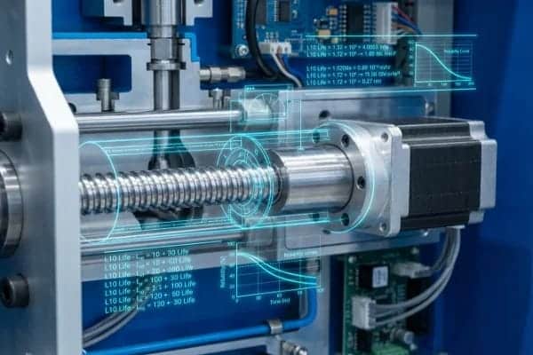
The Truth About Ball Screw "L10" Life Ratings
The ball screw is the muscle of an all-electric machine. However, not all screws are created equal. In the competitive machinery market, some suppliers cut costs by using undersized screws that look adequate but cannot handle the continuous load of 24/7 cycling.
To verify quality, you must demand the "L10 Life" calculation. This is a standard engineering statistic representing the number of hours that 90% of a group of identical ball screws will achieve before metal fatigue 1 occurs.
- Reliable Standard: A robust machine should use screws oversized to achieve >50,000 operational hours at maximum load.
- Le risque : Lower-tier machines often use screws rated for only 20,000 hours. In a factory running three shifts, this could mean a catastrophic seizure in less than three years.
Toggle System Bushing Material
The environment inside a blow molding factory is inherently dusty due to resin grinding and regrind usage. This dust is the enemy of moving parts. We strongly advise against standard steel-on-steel bushings for the toggle system. These require heavy, messy greasing that acts as a magnet for abrasive dust, creating a "grinding paste" that wears down the linkage.
Instead, look for Graphite-Impregnated Bronze bushings. These are self-lubricating 2 and run cleaner, significantly reducing wear in dusty environments.
Precision Belt Tensioning via Sonic Frequency
Many electric drives use belts to transfer power from the servo motor to the ball screw. A common maintenance mistake is checking tension by hand (deflection). This is inaccurate.
- Too Loose: Causes slippage and positioning errors.
- Too Tight: Destroys the motor bearings rapidly.
Reliable maintenance manuals must specify tension in Hertz (Hz). Your maintenance team should use a sonic tension meter 3 to tune the belt like a guitar string.
| Composant | Standard Specification | High-Reliability Specification (LEKA Standard) | Impact on Production |
|---|---|---|---|
| Ball Screw | Undisclosed or <25k hours L10 | >50,000 hours L10 Rating | Prevents early mechanical seizure. |
| Toggle Bushing | Steel-on-Steel | Graphite-Impregnated Bronze | Reduces wear from abrasive plastic dust. |
| Belt Tension | Manual Deflection (Thumb test) | Sonic Frequency (Hz) Metering | Extends servo motor bearing life. |
How Does Thermal Management Impact Servo Drive Stability Under Full Load?
Our engineers have found that heat is the silent killer of servo drives and control electronics. Without rigorous thermal management, electronic components degrade rapidly, especially during hot summer months in non-climate-controlled factories.
Thermal stability requires an industrial air conditioner on the electrical cabinet to maintain temperatures below 35°C. Additionally, check for "Active Front End" technology that returns braking energy to the grid rather than using internal resistors, preventing heat soak that damages sensitive control electronics.

Active vs. Passive Cabinet Cooling
Electronics hate heat. The capacitors inside servo drives 4 have a lifespan that is directly tied to operating temperature. For every 10°C rise in temperature, the life of a capacitor is cut in half.
Many budget machines rely on passive filter fans. This acts like an open window; it sucks in hot, humid, and dusty factory air. This leads to two problems:
- Thermal Derating: When the cabinet gets too hot (>40°C), servo drives automatically limit their power output to protect themselves, causing cycle times to slow down unpredictably.
- Short Circuits: Dust and humidity drawn in by fans can cause short circuits on PCBs.
We recommend ensuring the main electrical cabinet is equipped with a dedicated Industrial Air Conditioner. This creates a sealed, cool environment (maintained at 35°C) regardless of how hot your factory floor becomes.
Managing Regenerative Energy
Electric machines accelerate and decelerate rapidly. When a heavy mold stops closing, that kinetic energy must go somewhere. This is regenerative braking 5.
- The Problem (Braking Resistors): Older or cheaper designs dump this energy into braking resistors 6, essentially giant heaters. If these are mounted inside the cabinet, they cook the electronics.
- The Solution (Active Front End – AFE): Modern reliable systems use an AFE drive. This converts the braking energy back into electricity and returns it to the factory grid. This not only saves energy but eliminates a massive heat source from the machine.
Compensating for Thermal Growth
Friction generates heat. As a machine runs 24/7, the ball screws naturally heat up and physically expand (elongate). On a long screw, this growth can be significant enough to change the mold closing position by microns, affecting tonnage and "parting line" quality.
Top-tier control systems use Thermal Compensation Logic. The controller predicts or measures the heat and automatically adjusts the target position. This ensures that the bottle you produce at 8:00 AM is identical to the one produced at 8:00 PM, without manual operator adjustment.
What Are the Hidden Failure Points in Wiring and Lubrication Systems?
In our experience exporting to the US and Europe, minor oversights in cabling or lubrication systems cause the majority of downtime events. These "hidden" systems require strict auditing during your pre-shipment inspection.
Prevent common failures by verifying that cable drag chains have a bend radius 8–10 times the cable diameter. You must also ensure the automatic lubrication system uses point-level flow sensors to detect individual blockages, and prioritize battery-less absolute encoders to avoid recalibration after power loss.
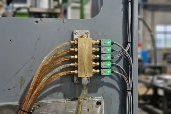
Audit the Automatic Lubrication System (ALS)
Grease starvation is the number one killer of mechanical components. A standard lubrication system has a pump and a distribution block. The pump pushes grease, and a pressure sensor says "OK."
The Critical Flaw: If one line to a toggle pin is clogged, the pump pressure will still rise, so the machine thinks everything is fine. Meanwhile, that single pin is running dry and will eventually seize.
La solution : You need "Point-Level" Feedback. This involves individual flow sensors or piston detectors on chaque distribution block. If a single line fails to deliver grease, the machine should alarm immediately, pinpointing exactly which bearing is at risk.
Cable Management Standards
In an electric machine, power and data cables are constantly moving inside drag chains 7. Copper fatigue is inevitable if the design is poor.
- Bend Radius: The track radius must be at least 8 to 10 times the diameter of the thickest cable. Anything tighter stresses the copper, leading to internal breaks that are impossible to see but cause intermittent faults.
- Separation: Power cables (high voltage) can create "noise" that interferes with data cables (encoders). They must be physically separated by dividers within the chain.
- Class 6 Rating: Verify the cables are rated for "Continuous Flex" (Class 6). Standard cables will crack within months.
The "Battery-Less" Advantage
Imagine a power outage hits your factory on a Sunday. On Monday morning, you restart the machine, but it has lost its "Home" position because the backup batteries in the encoders 8 died. Now you face hours of complex mechanical recalibration.
This is a common headache with older servo technology. To ensure high availability, insist on Multi-turn Absolute Encoders that are Battery-Less (using optical or magnetic gears). These remember their position mechanically, meaning the machine is ready to run immediately after power is restored, regardless of how long it was off.
Predictive Maintenance: Grease Ferrography
For those looking to move from "reactive" to predictive maintenance 9, ask if the design supports Grease Ferrography. This is like a blood test for the machine. By collecting old grease purged from the ball nut and analyzing it under a microscope, you can see metal particles.
- Spherical particles: Indicates fatigue failure (spalling).
- Cutting wear particles: Indicates abrasive contamination.
This allows you to detect a failing screw months before it actually jams, allowing you to order a replacement part during scheduled downtime rather than in a panic.
| Fonctionnalité | Standard "Risky" Configuration | Reliable "Safe" Configuration |
|---|---|---|
| Lubrication Monitoring | Main pump pressure only | Individual point flow sensors |
| Encoder Type | Incremental or Battery-Backup | Battery-Less Absolute (Magnetic/Optical) |
| Cable Chain | Tight radius, mixed cables | 8-10x Radius, Class 6 Flex, Separated |
Conclusion
Reliability in all-electric blow molding isn’t about luck; it’s about engineering verification. By auditing L10 screw ratings 10, insisting on active thermal management, and demanding battery-less encoders, you ensure your investment delivers consistent profits rather than constant maintenance headaches.
notes de bas de page
1. Explanation of common metal fatigue failure modes in engineering. ↩︎
2. Benefits of oil-impregnated bronze for maintenance-free operation. ↩︎
3. Overview of sonic tension metering for precision belt drives. ↩︎
4. Technical principles of servo drive operation and control. ↩︎
5. Comparison of regenerative versus dynamic braking systems. ↩︎
6. Function and heat dissipation of dynamic braking resistors. ↩︎
7. Design guidelines for energy chains and cable carriers. ↩︎
8. Understanding absolute versus incremental encoder technology. ↩︎
9. Strategies for implementing predictive maintenance in manufacturing. ↩︎
10. Methodology for calculating bearing L10 rating life. ↩︎


0 commentaires