


At LEKA Machine, we frequently warn clients that "all-electric" systems still rely heavily on compressed air, creating a risk of failure if moisture management is ignored corrosive acidic emulsion 1.
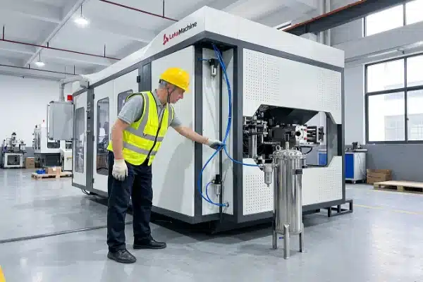
To verify an oil-water separator, trace the condensate drain lines from the air receiver to a standalone filtration unit. Ensure it features a cyclonic depressurization chamber, oleophilic filter cartridges, and a dual-exit architecture for separating waste oil from purified water before discharge.
Understanding the nuances of air preparation is the only way to protect your investment ISO 8573-1 Class 1-2-1 2.
Why is an oil-water separator critical for protecting the pneumatic valves in an all-electric machine?
Our engineering team often troubleshoots expensive "electronic" failures that are actually caused by sludge clogging the precision proportional valves 3 within the pneumatic circuit.
An oil-water separator is critical because compressed air creates a corrosive acidic emulsion of water and synthetic oil. Without separation, this sludge washes out valve lubrication, swells elastomeric seals, and causes "stiction" in high-speed proportional valves, leading to erratic bottle weights and machine seizure.

The "All-Electric" Paradox and Toxic Sludge
The marketing term "all-electric" can be deceptive. While servo motors drive the carriage, clamping, and extrusion, the fundamental blowing of the bottle—and often the stretching, deflashing, and ejection—relies on high-pressure air. This creates a critical vulnerability. When a compressor operates, it concentrates ambient humidity and trace amounts of lubricating oil.
As this mixture cools, it condenses into a toxic emulsion. This isn't just dirty water; it is an acidic, viscous sludge. In our experience, when this sludge bypasses filtration, it attacks the machine in three specific ways:
- Lubrication Washout: The water content strips away the factory grease inside pneumatic cylinders and valves.
- Chemical Attack: Synthetic compressor oils can react with rubber seals (O-rings), causing them to swell or crack.
- Mechanical Stiction: The sludge creates a sticky residue that prevents high-speed valves from opening or closing smoothly.
Failure Modes in Precision Components
Modern blow molding machines use proportional valves to control parison thickness. These valves operate with extremely tight tolerances. Even microscopic contaminants can cause them to jam or move sluggishly (stiction).
When a valve sticks, the parison thickness becomes uneven. You might spend weeks adjusting servo settings, thinking it is a software issue, when it is actually a pneumatic hygiene issue. Below is a breakdown of how untreated air damages specific components.
Table: Impact of Contaminated Air on Machine Components
| Componente | Failure Mechanism | Operational Consequence |
|---|---|---|
| Proportional Valves | Spool stiction and orifice clogging | erratic parison control; uneven wall thickness. |
| Pneumatic Cylinders | Seal swelling and rust accumulation | Slow cycle times; jerky movement; air leaks. |
| Blow Pin / Needle | Oil mist injection | Product contamination (rejects in food/pharma). |
| Silencers/Mufflers | Pore clogging | Increased back pressure; slower exhaust times. |
If you are producing food-grade or pharmaceutical bottles, the risk is even higher. Oil vapor that bypasses the separator can enter the bottle during the blowing phase, leading to immediate batch rejection and potential regulatory fines.
How can I visually inspect the air preparation unit during the Factory Acceptance Test?
During pre-shipment trials at our Shantou facility, we guide clients to look beyond the HMI screen and physically inspect the air treatment train located at the machine's inlet.
Visually inspect the air preparation unit by confirming the presence of a multi-stage FRL (Filter-Regulator-Lubricator) assembly. Check for automatic bowl drains, differential pressure gauges on filters, and a dedicated oil-water separator unit connected to the compressor’s condensate discharge, not just a simple moisture trap.

conducting the "Traceability Test"
A common trick in the industry is to install a simple moisture trap and call it a separator. During the Factory Acceptance Test 4 (FAT), you must perform a traceability test. Do not just look at the machine; look at the piping connecting the compressor to the machine.
You are looking for a specific sequence of components. The air should not go straight from the compressor to the machine. It must pass through a dryer and a series of filters.
H3: The Anatomy of a Proper FRL Service Unit
On the machine frame itself, locate the pneumatic inlet. You should see a cluster of components known as the FRL (Filter, Regulator, Lubricator). However, for blow molding, a "Lubricator" is often dangerous for the blow side (causing contamination), so you are specifically looking for advanced filtration.
Verify the following visual cues:
- Automatic Drains: Look at the bottom of the filter bowls. Are there wires or float mechanisms? If there are only manual twist-drains, your operators will likely forget to open them, and water will flood the system within hours.
- Differential Pressure Indicators: Good filters have a small gauge on top. It acts like a traffic light. Green means good; red means the filter is clogged. If these are missing, you have no way of knowing when to change the element.
- Colorimetric Indicators: Some high-end separators have a sight glass with moisture-sensitive beads. They should be blue. If they are pink or white during the FAT, the air is wet, and the system is failing.
Table: FAT Visual Inspection Checklist for Pneumatics
| Inspection Point | What to Look For | Pass Criteria |
|---|---|---|
| Condensate Drains | Bottom of air receiver & filters | Automatic/Electronic drains (not manual valves). |
| Filter Bowls | Material of construction | Metal guards or stainless steel (polycarbonate can crack). |
| Pressure Gauges | Across filtration stages | < 0.1 bar drop (indicates clean elements). |
| Oil-Water Separator | Discharge lines | Dual output: Clean water to drain, oil to waste tank. |
| Bypass Valves | Around dryer/filters | 3-valve bypass present for servicing without shutdown. |
When testing, ask the technician to manually trigger the drain. It should expel liquid forcefully. If nothing comes out, or if it continuously hisses, the separator mechanism is likely faulty or blocked by debris.
What specifications should I look for to ensure the separator handles my factory's humidity levels?
We advise customers in humid regions like Southeast Asia that standard dryer ratings often fail because they ignore ambient temperature and relative humidity spikes during summer months.
Ensure the separator specification accounts for your factory’s worst-case ambient temperature and humidity, not just the machine's nominal airflow. You must verify compliance with ISO 8573-1 Class 1-2-1 standards, specifically requiring a pressure dew point of -40°C and oil removal to 0.01 mg/m³.

Understanding ISO 8573-1 Standards
You do not need to be a chemical engineer, but you do need to know one number: ISO 8573-1 Class 1-2-1. This is the gold standard for high-quality blow molding.
- Class 1 (Solids): Filters out particles smaller than 0.1 microns. This protects your valve spools from scratching.
- Class 2 (Water): Requires a Pressure Dew Point 5 (PDP) of -40°C. This prevents water from condensing even if the air expands rapidly and cools down.
- Class 1 (Oil): Limits oil content to 0.01 mg/m³. This is non-negotiable for food safety and preventing seal rot.
If your supplier quotes a "standard commercial dryer," it likely only achieves Class 4 for water (+3°C dew point). In a cold factory or during rapid decompression, this will still allow water to form in your mold, causing surface defects on your bottles.
H3: The Trap of SCFM vs. ACFM
A major pitfall in sizing these systems is relying on Standard Cubic Feet per Minute (SCFM). SCFM measures air at "perfect" conditions (usually 20°C, 0% humidity).
However, if your factory is in Texas or Thailand, your intake air might be 35°C with 90% humidity. The actual amount of water your separator needs to remove is massive compared to the standard rating.
When verifying specs, ask for the Correction Factors used.
- If the inlet temperature is 38°C (100°F) instead of 38°C, the dryer capacity might drop by 15%.
- If the system pressure is lower than 7 bar, the air moves faster, and the dryer becomes less efficient.
Table: ISO 8573-1 Recommendations for EBM Machines
| Purity Class | Contaminant | Limit / Specification | Why it matters for EBM |
|---|---|---|---|
| Class 1 | Solid Particles | ≤ 0.1 micron | Prevents scoring of servo-pneumatic valve spools. |
| Class 2 | Water | -40°C Dew Point | Prevents condensation inside the cold mold cavity. |
| Class 1 | Oil Aerosols | ≤ 0.01 mg/m³ | Protects rubber seals and ensures food-grade safety. |
Always oversize your air treatment system by at least 20-30% above the machine's maximum consumption to account for these environmental variances and filter aging.
How do I ask the supplier about the maintenance schedule for the air filtration system?
When we hand over a machine, we emphasize that skipping filter changes is the fastest way to destroy expensive servo-pneumatic components and void the warranty.
Ask your supplier for a detailed maintenance schedule that specifies replacement intervals for coalescing filter elements and oil-water separator carbon media. Request part numbers for the "Crash Kit" and inquire about IIoT integration for monitoring differential pressure to predict filter failure before downtime occurs.

Moving from Reactive to Preventive Maintenance
The air system is often the most neglected part of the factory because it sits silently in the corner. By the time you notice water in your machine, the damage is already done. The valves are already washed out, and rust has already formed in the pipes.
You need to demand a maintenance schedule that is integrated into your machine's daily operations. Do not accept a generic manual. Ask for a specific Air Treatment SOP (Standard Operating Procedure).
H3: Critical Maintenance Intervals
Your supplier should provide a schedule similar to this:
- Daily: Check auto-drains. If an auto-drain is stuck open, you are wasting expensive compressed air. If it is stuck closed, you are flooding the system.
- Weekly: Check the differential pressure gauges. A sudden jump indicates a collapsed filter element or a surge in compressor oil carryover.
- Semi-Annually: Replace the carbon bags in the oil-water separator 6. These bags absorb the oil so the water can be legally drained. Once they are saturated, you are dumping oil into the sewer, which is an environmental violation.
- Annually: Replace all coalescing filter elements 7, regardless of how they look. Micro-fibers break down over time and can migrate downstream into your valves.
H3: Leveraging IIoT for Predictive Care
At LEKA Machine, we encourage clients to use smart sensors. Instead of walking around checking gauges, modern systems can connect to the machine's PLC or a cloud dashboard.
You should ask: "Does this machine track air pressure drops digitally?"
If the answer is yes, you can set an alarm. When the filter is 80% clogged, the maintenance manager gets a notification. This allows you to order parts and schedule the change during a planned shift change, rather than stopping production during a rush order because a valve seized up.
Finally, ensure your "Crash Kit" (the recommended spare parts list) includes at least one full set of replacement elements and a seal kit for the auto-drain valves. These parts are inexpensive but can take weeks to ship if you don't have them in stock.
Conclusión
Verifying the oil-water separator is not just about compliance; it is about survival for your all-electric EBM machine. By inspecting the FRL, demanding ISO Class 1-2-1 specs, and adhering to a strict filter maintenance schedule, you ensure stable production and protect your high-precision valves from catastrophic failure.
Notas al pie
1. Explains how acidic condensate forms in compressed air systems and causes corrosion. ↩︎
2. Details the international standard for compressed air quality, including particle, water, and oil classes. ↩︎
3. Describes the function and applications of proportional valves in pneumatic systems. ↩︎
4. Defines the Factory Acceptance Test (FAT) process in manufacturing and its importance. ↩︎
5. Explains the definition and importance of pressure dew point in compressed air systems. ↩︎
6. Explains the purpose, components, and working principle of industrial oil-water separators. ↩︎
7. The original URL from Brother Filtration is now working and explains what a coalescing filter is and how it works. ↩︎


0 Comentarios