
How to Verify Neat and Compliant Cabling in All-Electric Extrusion Blow Molding Machines?
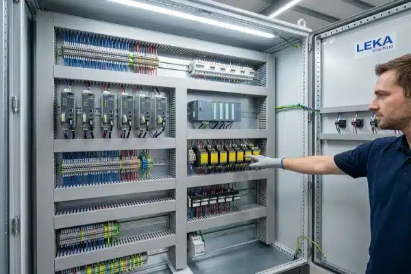
At our assembly plant, we know that a machine’s reliability depends heavily on what is hidden inside the electrical cabinet. When customers visit us for factory acceptance 1, we encourage them to look beyond the mechanical movements and inspect the wiring logic, because sloppy cabling is often the first sign of future downtime.
To verify compliance, start by auditing the data plate for system-wide CE/UL certification rather than just component markings. Inspect the physical segregation of high-voltage power lines from low-voltage data cables to prevent interference. Finally, confirm the cabinet utilizes active cooling to protect sensitive servo drives from heat and dust.
Let’s break down the specific checkpoints you need to inspect to ensure your new all-electric machine is safe, compliant, and easy to maintain.
Do the Electrical Cabinets Meet CE or UL Safety Standards?
When we export machines to Europe or North America, we adhere to strict design protocols because we understand that safety inspectors will flag non-compliant systems immediately. We design our electrical layouts to ensure that passing a local field inspection is seamless for our clients.
You must confirm that the entire control cabinet assembly is UL/CE certified as a complete system, not just the individual breakers or contactors inside. Additionally, verify that servo motor cable shields are grounded with 360-degree EMC clamps to the backplane, avoiding twisted pigtails that compromise signal integrity.

The Trap of "Component Only" Certification
One of the most common issues we see in the industry is the confusion between component certification and system certification. A supplier might claim their machine is "CE Certified" simply because the Schneider Electric breaker inside has a CE mark 2. This is misleading.
To be truly compliant, the entire cabinet assembly must be certified. This means the design, thermal calculations, wire sizing, and protection logic have been audited as a whole unit. Always check the main machine data plate. If it does not explicitly state compliance for the assembly, your local inspector may shut down the machine until you pay for an expensive field evaluation.
Strict Voltage Segregation
In all-electric blow molding machines, electromagnetic interference (EMI) 3 is a silent killer of performance. Servo drives generate significant electrical noise. If high-voltage power cables run parallel to sensitive low-voltage data cables, that noise will corrupt your signals, leading to phantom errors or erratic parison control.
We strictly follow segregation rules in our wire ducts. You should open the wire ways and look for physical separation.
EMI and Grounding Techniques
For an all-electric machine, proper grounding is not just about safety; it is about performance. You must inspect how the shielded cables 4 from the servo motors are terminated.
- Bad Practice: The technician twists the wire mesh shield into a "pigtail" and screws it to the ground bar. This acts as an antenna for noise.
- Good Practice: The shield is clamped using a 360-degree EMC metal clamp directly to the conductive backplane.
Voltage Separation Guidelines
Use the following table to verify if the machine wiring meets standard separation distances.
| Cable Category | Example Voltage | Required Separation |
|---|---|---|
| High Power | 480V / 230V AC (Servo Power) | Must be in a separate duct or separated by a grounded metal divider. |
| Control Power | 110V AC / 24V DC (Coils/IO) | Can run near high power only for short distances if shielded. |
| Data/Signal | Ethernet / 0-10V Analog / Encoder | Strict Isolation. Never run in the same conduit as 480V power. |
How Is the Control Cabinet Protected Against Dust and Heat Buildup?
Our engineering team learned early on that plastic processing environments are harsh. The fine polymer dust generated by grinders and the ambient heat from extruders can destroy sensitive electronics. We build our cabinets to survive these conditions, not just a cleanroom environment.
Ensure the cabinet is rated at least IP54 and uses an active air conditioning unit or heat exchanger instead of simple filter fans. Verify that cable entry points use tight-fitting rubber glands to seal against dust, and check that there is at least 20% spare space on DIN rails for airflow.
Active Cooling vs. Filter Fans
All-electric machines rely heavily on servo inverters. These components generate heat—a lot of it. In a standard blow molding factory, the ambient temperature can easily reach 40°C (104°F) in summer.
If the machine uses simple filter fans 5, two things happen:
- Clogging: The fans suck in polymer dust, clogging the filters. Airflow stops, and the drives overheat and trip.
- Heat Soak: If the factory air is 40°C, the fans cannot cool the cabinet below 40°C. Electronics degrade faster at high temperatures.
We recommend and use Active Cabinet Air Conditioners. These units circulate internal air through a closed loop, keeping dust out while actively refrigerating the cabinet to a stable 30°C–35°C.
Managing Cable Entry Points
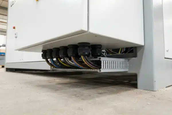
Look at the bottom or top of the cabinet where the cables enter the machine frame. This is often a weak point. If cables simply pass through a rough hole, vibration will eventually cut through the insulation, causing a short circuit.
You must verify two things:
- Strain Relief: Cables should be secured so that pulling on the outside cable does not stress the connection inside the terminal block.
- Sealing: Use rubber cable glands 6 or modular cable transit systems. This prevents dust and rats from entering the cabinet.
Space for Airflow and Expansion
A neat cabinet is not just about looks; it is about thermal management. A cabinet packed 100% full is a bad sign.
- Heat Dissipation: Servo drives need empty space above and below them to allow hot air to rise. If wire ducts are jammed against the drive vents, they will fail.
- Future Proofing: We ensure there is 20% "Spare Real Estate" on the DIN rails 7. This allows you to add future automation, extra sensors, or safety relays without replacing the whole cabinet.
Cooling System Comparison
Here is a comparison of why we choose active cooling for high-performance machines.
| Feature | Simple Filter Fan | Active Heat Exchanger | Cabinet Air Conditioner |
|---|---|---|---|
| Cooling Power | Low (Ambient Air) | Medium (Ambient Air) | High (Refrigerated) |
| Dust Protection | Poor (Sucks in dust) | Good (Closed Loop) | Excellent (Closed Loop) |
| Maintenance | High (Clean filters weekly) | Low | Low (Clean condenser monthly) |
| Best For | Clean, cool rooms | Light dust areas | Hot, dusty factory floors |
Can I Inspect the Wiring Organization During the Factory Acceptance Test?
During the Factory Acceptance Test (FAT) at our facility, we hand the client the electrical schematic and invite them to audit the machine. We believe that if you cannot trace a wire now, you will lose thousands of dollars in downtime trying to trace it later when the machine stops.
You should conduct a "tug test" on random terminal blocks to check for loose connections and perform an audit matching wire labels to the schematic. Furthermore, request an Infrared (IR) Thermography scan while the machine runs at full load to instantly identify invisible hot spots caused by poor contact.

The Wire Labeling Audit
Troubleshooting a machine with unlabeled wires is a nightmare. During the FAT, do not just watch the machine make bottles. Open the electrical drawings 8.
Pick 5 to 10 wires at random in the cabinet.
- Does the alphanumeric tag on the wire match the tag on the drawing?
- Is the label on both ends of the wire?
- Is the label readable and durable, or is it falling off?
If the labels don’t match the drawings exactly, refuse to accept the machine until they are corrected. Mismatched labels will drastically increase your repair time during a breakdown.
The "Tug Test"
Loose connections are a common cause of arcing and fire. Factory workers can get tired and fail to torque screws properly.
- Action: Gently wiggle wires connected to breakers, contactors, and terminal blocks.
- Result: The wire should feel solid. If it moves or comes out, the connection is bad. We train our team to use torque screwdrivers, but a physical check is the only way to be sure.
High-Flex Cabling for Moving Parts
In extrusion blow molding, the mold clamping unit moves back and forth millions of times a year. Standard copper cable is not designed for this. It will work for a few months and then snap internally, causing intermittent faults that are hard to find.
Verify that all cables inside the drag chains (cable tracks) are rated as "High-Flex" or "Continuous Flex" cables. These are designed with finer copper strands and special jackets to withstand continuous bending 9.

Infrared (IR) Thermography
The best way to see a loose connection is with heat. Ask us (or your supplier) to run the machine at full load for an hour. Then, use a thermal camera 10 to scan the electrical cabinet.
- What to look for: A bright red or white spot on a terminal connection.
- Meaning: High resistance due to a loose screw or a bad crimp. This is an immediate fail that needs correction.
FAT Electrical Checklist
Use this simple checklist during your next machine acceptance.
| Inspection Item | What to Check | Acceptance Criteria |
|---|---|---|
| Wire Labeling | Select 10 random wires. | 100% match with electrical schematic. |
| Terminal Security | Perform "Tug Test" on power cables. | Zero movement; wires remain secure. |
| Moving Cables | Check cables in drag chains. | Must be rated "High-Flex" / "Continuous Flex". |
| Thermal Scan | IR Scan under load. | No hotspots >10°C above ambient on terminals. |
Conclusion
Verifying compliant cabling ensures safety, reduces downtime, and simplifies future maintenance.
Footnotes
1. Explanation of standard testing procedures used to validate equipment before shipment. ↩︎
2. Details on the European conformity marking and its regulatory requirements for machinery. ↩︎
3. Definition of electrical noise and its negative impact on industrial automation systems. ↩︎
4. Guide to how cable shielding protects signals from electromagnetic interference. ↩︎
5. Comparison between passive fan cooling and active cooling units for enclosures. ↩︎
6. Technical data on mechanical cable entry devices and ingress protection. ↩︎
7. Overview of standard mounting rails used for industrial circuit breakers and controls. ↩︎
8. Basics of reading and interpreting construction and manufacturing electrical plans. ↩︎
9. Differences between standard static cables and cables designed for continuous motion. ↩︎
10. How thermal imaging is used to detect invisible electrical faults and hotspots. ↩︎